Technical Projects


MATLAB
Image Modification

Fall 2025
MATLAB
Temperature Analysis
Fall 2025

Intro To C Programming
Final Project

Spring 2025

Overview
In an Introduction to C-Programming class that I took at the University of Colorado Boulder, I completed an end-of-semester project to showcase all that I had learned throughout the class. While the class primarily focused on an understanding of the programming language C, we also learned how to utilize Bash commands, as well as a Linux terminal. Additionally, to compile multiple C files of a big program in one command, we refactored files into libraries and used the Make utility to execute everything.
Guidelines
A text-based adventure game (printed in a Linux terminal)! The project's simple guidelines were to create a game where a player traverses a few unique rooms, while simultaneously picking up items and accumulating a score. As a player, the goal should be to finish with the highest score possible. Some additional guidelines for the project were to ensure that the program constantly printed information about the player(i.e., current location or available items) and that the player could type in their own commands. The goal for the project was to give the player complete control and freedom of how they wanted to play. Furthermore, libraries and refractored code had to be implemented to ensure a compact main file, along with the ability for others to easily understand the game's logic. If you would like more details, the full project rubric and description can be found by clicking HERE!
Design Process
To complete this project in a more manageable approach, I broke everything into smaller steps and completed each of them one at a time. This allowed me to focus on the details of each section within the wide scope of the project, ensuring a polished final product...


Primary Structs
While-Loop
Scanf() Function
Command Input Algorithm

Step 1 - Core Functionality
First, when determining how I was initially going to build this project, it became clear that the game's core functionality was heavily reliant on a player moving from one room to another. Therefore, I got started on player movement first. When it came to storing the information regarding the player, I made sure to save it within a C struct. This would allow me to access the player's data globally within the rest of my program, so long as I included the player library in each of my subsequent files. I began this project with one singular main file in a new JupyterLab instance. With this new file in hand, I created the _player struct, stored it on the heap, and used the typedef struct function to swap the name throughout the remainder of the file to be recognized as the Player struct. Within the Player struct, I assigned variables to give more detail about the player. Some of the variables included were name, score, position, and health. I then wrote in a few primary functions, allowing the code running in the main() function to interact and assign values to each of these variables. Then, for each of the rooms that I wanted to add to my game, I created similar structs. Each of these room structs was once again stored on the heap, and each contained specific information about the respective room. From here, with the structs for each room and player created, I developed the framework for a simple printed menu system using the scanf() function. This would allow the player to enter a number in the Linux terminal, in turn selecting their desired action, and then execute their respective command. The entire logic of the program functioned on one big while loop within the main() function. If the while loop terminated, the game was over. For example, say a player wanted to move up or move down a room. They would enter a 1 or a 2. If they were in a specific room, they could type a 3 to learn about their current location or a 4 to enter the room (to later fight monsters or pick up objects). If the player wanted to end the game with their current score, they could type a 5, and the while loop would terminate. Even though I had only completed a simple framework of the project at this point, the core functionality of player movement was complete.
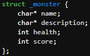
Step 2 - Monsters & Objects
The next big item on the to-do list was assigning specific inventory Objects and Monsters to each room. That way, a player would have a way to increase their final score, and the game would have some added complexity. In a nutshell, I again used structs for each monster and object type. Each object and monster I created had a few parameters (name, description, and possibly health/score) that I could easily access using functions similar to those that I had previously used for the rooms and player. I then added an array of pointers to Object types and an array of pointers to Monster types within each room's struct. This allowed me to specifically assign a unique set of Monsters and Objects to each room. From there, in a separate file that initialized at the start of the game, before the player could input any commands, I assigned a hardcoded array of monsters and objects to each room. This ensured that as the player progressed from room to room, they could see and interact with each room's respective Monsters or Objects. From this point, I reworked my initial command input and printing algorithm to allow for different logic paths to be taken. If the player chose to fight a monster, the program would prompt them to select which monster they would like to fight, and a while loop would commence until either the player's health or the monster's health had been depleted. If the player chose to pick up an item, another while loop would initialize and terminate only once the player had decided which item to pick up. Taking a deeper dive into the fighting sequence, it was randomized using the random() function in C. While the random() function typically returns a massive random number without any limitations on its maximum output, using the computer's current time as well as online forums and blogs, I converted the function to output a random number between 0-X, where X was the top of the ouput range. From here, I used the modified random function to give the player a 50/50 shot of their attack landing. If the attack hit and landed on the monster, the monster would lose 10 health. However, if the attack missed, the monster would then attack the player, and the player would lose 10 health. Now, moving to the logic behind the item pickup system. If the player chose to pick up an item within a room, they would be prompted to select the item they would like to pick up. The item would then be placed into their inventory, so long as they had open slots. For both the fighting menu and the item pickup menu, they were adapted using my previously developed menu for player movement between rooms. Finally, the last piece of code that I needed to add was to allow the player to use an item. When building the secondary menus for the player, I added another option, again by typing in a different number, to let the player decide if they would like to use an item in their inventory. Then, if they chose to use an item, the program would open another nested menu, prompting them to select which item they would like to use. Since the only items in my game were stat increasers (health or score boosts) or damage increasers (sword), when a player used an item, I would run corresponding functions to adjust the values within the player's struct. This ensured that their use of an item would have a global effect across the whole game, and not just for that singular instance. After finishing all of the secondary menus and different logic paths for the player to select from, the complexity behind adding monsters and objects to the game was complete.

Primary Structs

Object & Monster Creation

Item-Pickup Function
Monster-Fight Function


Makefile

File
Explorer
Step 3 - Refactoring & Make File
After designing and completing the majority of the code for the project, it was time to organize things. For starters, I moved the player struct and all of its corresponding functions into a completely separate file, player.c. Additionally, I added another file, player.h which would act as its library, containing all of the function definitions inside of player.c. This process, moving code into separate files and creating libraries for them, is called refactoring. By organizing all of the code for the project in this way, I knew exactly where to go to modify anything relating to an overarching type (player, room, monster, or object) in the program. If I wanted to use type-related functions in another file, all I had to do was include the library at the top of the file, and all of type's the corresponding function definitions would be included at compilation. Refactoring also allowed me to separate the functions responsible for the player's initial creation from the functions that adjusted the player's structure while the game is played. Furthermore, print statements, random functions, and all objectCreation, monsterCreation, and roomCreation related functions were separated into their own refactored libraries as well. That way, I could easily determine which files I needed to look at to modify the room, monster, or object structs directly. Refactoring my code allowed me to easily make modifications in the future while ensuring that I only imported the necessary code for each additional file I created. Additionally, by compiling each file into its own object file and then linking all the compiled object files together to create one executable, I significantly reduced the time required for the entire project to compile. I only had to compile files that had recently obtained changes. After I refactored all of my files into different libraries, I created a simple makefile, through the use of GNU Make, which allowed me to compile my full program with the command "make" in the Linux terminal. Essentially, the reason Make was so powerful here was that it called the compiler to compile all of the object files needed for the project to run, linked them together, and did it all with one command. I didn't have to compile each file individually or link them together afterward. Additionally, with Make, it automatically detected which files had been modified after the most recent compilation. Therefore, Make would only compile the files that had been saved after the most recent compilation. This allowed for even quicker program compilation, as, again, I didn't have to check manually! After running "make", all I had to do was run the executable via the Bash command, "./main" within the Linux terminal for the game to begin. Overall, through the use of separate compilation, refactorization, and a makefile, I was able to improve the overall layout and efficiency of my code while ensuring that it could be easily modified in the future.
Step 4 - Polish
Finally, after cleaning up and finishing the core functionality of the project, I added a few more things to make the game shine! I first added loot pools to the MonsterCreation and ObjectCreation files. This allowed me to use the previously created randomizer function to randomize the objects and monsters associated with each room. By doing this, a more unique and replayable experience was available! Every time the player ran the startup command in Bash, a new set of objects to pick up and monsters to fight was available! I then added a few unit tests to run at the beginning of my game to ensure that both my movement and score functions worked properly. Additionally, in each room and on the main menu screens, I added a multitude of pictures and artwork via an ASCII image converter. This gave the game more pop and a true adventure-like feel. The player could truly visualize what was going on. Finally, to truly seal the deal, I added more instructions and adjusted the location of certain print commands. This not only gave the game a uniform and pristine look, but it also gave the player an easy way to find the information they needed! With the completion of these final items, the game and overall design were complete!

ASCII Images
Dashed
Format
Video Breakdown
For this project, I was required to submit a video of myself explaining and playing my game. I welcome you to watch it below if you would like to get a better understanding of how it works!
GitHub Repository
If you would like to see the code yourself, you are welcome to visit my GitHub page, where it is saved! Please click HERE to view.
What I Learned
Overall, while a little stressful during finals week, this project was quite a bit of fun! Sure, initially getting started and trying to figure out exactly how I was going to build everything was tough, but I eventually figured it out. Sometimes, it's not the testing that's the hard part, but getting an initial idea and framework made in the first place. Additionally, while I may have mostly worked with C for this project, by getting a firm grasp on how a foundational coding language works, I am now better equipped to learn more languages in the future. Moving to the bigger picture, I now truly understand the saying, "If it ain't broke, don't fix it." There were many times throughout the building of this project when I was trying to refine an algorithm, and I ended up accidentally breaking my whole game. While I did figure out most of the issues and get my program back to where it was, I had caused a bigger headache than I would have solved. I know better for the future that there are times when you just have to compromise. Things aren't always going to be perfect, and you just have to roll with the punches to move on. As long as the major components and logic are working well, you can always refine more later. That brings me to my final point: I had assumed that for the entirety of this project, I would need to do everything myself. In truth, I was not alone! By simply attending office hours and asking my professor questions about problems that I didn't know how to tackle, I ended up saving myself many more headaches than I would have otherwise! To sum everything up, problems will always arise in engineering. Whether working on something as intricate as this software project or on something completely different, the real value comes down to the critical thinking performed when these challenges arise. Sometimes you may not know the answer to a problem right away, but that's okay! Taking the time to assess the challenge from a different angle is where the solution begins to present itself.

Intro to Digital & Analog Electronics
Group Project
Fall 2024

Overview
In my first semester studying Electrical and Computer Engineering at the University of Colorado Boulder, I completed a preliminary project course that focused solely on learning how to design and create within a team. The project that our group was tasked to complete, however, wasn't an ordinary passion project. The primary focus was to address a real-world problem and build something to help improve it. More specifically, we were to utilize the engineering design process to create a prototype that could assist those with disabilities, helping them to feel more included in activities that would otherwise single them out. Throughout the semester, I got to collaborate with my teammates, meet strategic deadlines, and fulfill design criteria, all the while documenting our progress along the way. Throughout this project, we were also introduced to many fundamental tools of the Electrical Engineering world, such as Arduinos, breadboard circuitry, OnShape, CorelDraw, and a slew of hardware tools.
Social Style Quiz
At the very beginning of the whole semester, everyone was separated into groups of 3-4, initially laid out by our professor. We then, within each of our newly formed teams, had to assign roles for ourselves. We had to elect a group leader and also determine what everyone's strengths and weaknesses were. To accurately determine this, everyone in the class completed a communication style quiz to better understand what type of thinkers we were. Did one have the social style of an Amiable, Analytical, Driver, or Expressive thinker? The quiz would give an overview to see if someone was more focused on ensuring every single task gets done, or if they tended to prioritize the intricate details, in addition to determining how assertive they were. For our team, seeing as I was the one with the most prominent Driver communication style, meaning I was very up front about ensuring that each portion of our project gets completed, I was elected to be our group's leader.

Problem
With the framework of our team set up, we got to work further defining our initial problem. Through our initial discussions as a team, we struggled to find something that we, as a group, wanted to work on. We weren't fully comfortable venturing into something completely new, but we were also struggling to find a group of stakeholders that we could help as well. After discussing our troubles with our professor, however, she tossed the idea of improving a family board game for those with motor disabilities. This sounded like an extremely viable project for all of us, and we were on board with it! Chutes and Ladders became our board game of choice, and with our clients in hand and our brains at the ready, we dug deeper into finding the parts of the game that were difficult for those with motor disabilities.

Initial LED Design
Design Criteria

Preliminary Plan & Design Criteria
When it came to those with motor disabilities and a board game, like Chutes and Ladders, the main conflict between the two was moving physical game pieces across the board. Therefore, when initially considering different ways to improve our version of Chutes and Ladders, we had to lay out some initial design criteria to ensure that our final prototype truly accomplished the needs of our stakeholders. First and foremost, we had to find a way to remove the need for players to physically move around the game board. This is where our first design criterion of a successful player interaction rate and our second design criterion of multiple player requirements came into play. They would allow us to measure whether or not our digitized prototype could effectively replicate the game's functionality. Next, we wanted to ensure that the physical form of our game wasn't too big or expensive for the average consumer to purchase. This would ultimately be why we also imposed a thickness limitation as well as a cost constraint. Furthermore, we added one final criterion to help alleviate potential issues when testing our prototype. While it might seem unnecessary at first, adding the final constraint to ensure that our design powered on each time gave us a boolean to determine whether or not our prototype was working from a hardware standpoint. Even though we had already implemented criteria to test the code and logic portion of our final prototype, we needed one more constraint to determine whether or not our design was even powering on in the first place. That way, if our prototype wasn't meeting all of our design criteria, we could easily pinpoint if it was due to a hardware/circuit issue or a software/logic issue. With our design criteria in hand, we got busy using paper and pencil to sketch out our ideas. When initially putting our ideas on paper, and after assessing similar projects from the past few years, we wanted to utilize programmable LEDs alongside an Arduino UNO to visualize the location of each player on the board. Simultaneously, we wanted to incorporate a programmable LCD screen to simulate a random number being "spun" each turn. We would then add two 3.5mm jacks to allow us to obtain input from an external push-button, begin the player's turn, and then automate the rest. For our initial design of the board, we went with a square-like design that had a total of 49 playable squares, each with a 1.32" x 1.32" area, and an LCD with the dimensions 3.81" x 2.32" placed on the right side. The trick here was that, by measuring the dimensions between each LED on our programmable LED strip, we could space out each game square in such a manner that would allow us to put exactly two LEDs per square on a fully unrolled LED strand. Then, we could snake the LEDs up the game board, removing the need for us to have to cut and solder a bunch of smaller LED strips together. After getting our bearings and a better understanding of how we wanted to build our prototype, we began researching the cost of our proposed items. With a quick few searches on Amazon, The Home Depot, and our local McGuckin Hardware store, we put together a Bill of Materials. Additionally, before getting started on anything else, we assembled a Gantt Chart to outline the tasks we needed to complete and in what order they should be completed in. Finally, after brainstorming, planning, and preparing, we were ready to move on to testing our initial thoughts, dimensions, and programmable LEDs.


Arduino & Breadboard Setup
Preliminary OnShape CAD Model
Preliminary Prototype
Once we had our initial plan ready to go, the first thing we did was get to work and test the programmable LEDs and Arduino UNO. In these early days of our project, our group was heavily focused on the core functionality of the game and ensuring that using programmable LEDs to represent player position was a viable option. To start, when our programmable LEDs arrived, it became extremely clear that our game squares were too small. Not only were the LEDs spaced much closer than we had originally thought, but we also needed to give breathing room to the edges of our squares so that the LED strip had some way to bend and snake around each line. First, in order to fix the cramped square size, we doubled the length and width of each square, and then allotted four LEDs, with two LEDs sliding behind the board. We then 3D printed out two game squares, using OnShape and CU Boulder's ITLL, each with the proper cutout holes. While at first, it seemed as if our idea was going to work for the two blanks, we still needed to add more breathing room to the sides of the walls of our game board. As we were commencing our initial testing with the programmable LEDs, our group began to divide the tasks that needed to be done, and seeing as I was our team's leader, I was in charge of making these assignments. First, I put one of our groupmates, Spencer, in charge of hooking up our LCD screen to a breadboard. Then, while he tied everything into the current Arduino setup that we had with our programmable LEDs, I assigned another one of our group members, Eduardo, to get started on the shell of our prototype in OnShape. Finally, I had the last member of our team, Mario, work on some administrative tasks, like updating our Gantt chart and logging all of our current progress in a LaTeX journal. As all of this was going on, I continued to work on our OnShape design and 3D print iterations of our current dimensions. By dividing and coordinating our work, we maximized our time in and out of the classroom. Once we had perfected the dimensions on our 2-game-square setup, our group moved into our foam board prototype stage.

Revised Design
Foam Board Prototype
After testing and refining the dimensions of each player square, it was time to scale everything up. With our adjusted game square dimensions, our group decided to lower the number of total game squares on the board from 49 to 25. This would allow us to keep the original components of the game, in addition to its core functionality, while keeping it in a portable size. Seeing as the tested 3D prototype only had the circuitry of two game squares, we needed to start by adding the LED circuitry for the remaining 23 squares. Additionally, as the Arduino, LCD screen, and programmable LEDs were all wired together via a breadboard, we needed to shift the wires to soldered perf boards. This would create a permanent and robust circuit design for our final prototype. To get a better understanding of what our final product would look like and to get a better guide for the wiring on our final prototype, we used a foam poster board. More specifically, we took a foam poster board and cut holes, simulating the proper location and measurements of each LED on the final prototype. I assigned both Mario and Eduardo to complete the cutting, hopefully ensuring the measurements could be as exact as possible. While the foam board construction was underway, I got busy assembling the circuitry for all of the programmable LED strips, and Spencer continued work on the code and logic for the game. In terms of the work that I specifically completed, I soldered jumper wires to the ends of each strip of LEDs, keeping the power jumper wires all on the left side, while the data jumper wire would snake back and forth, attaching the end of one LED strip to the beginning of the next strip just above it. Then, using some trimmed pin connectors and perf boards, I soldered all of the 5V jumper wires together and all of the GND jumper wires together. This powered and gave data to the entire LED circuit via the Arduino using only three wires, as opposed to the possible 15 (3 per strip). From here, I attached the newly soldered LED strips to the back of the foam board with some masking tape. At this point, the overall prototype was coming together! We could fully simulate a player pressing a button and moving their character across the foam board layout! Next, it was time to remove the breadboard.


Top View
Side View
Fine Tuning
With the foam board cutout complete and the wiring for the LED strips taped underneath, it was time to move the buttons, LCD screen, and potentiometer to perf boards. In our group, I handled the majority of the soldering work. Out of all of the components, the hardest one to solder was the LCD screen. This was due to the sheer number of close-proximity jumper connections to our LCD. If one small bubble of solder happened to land in the wrong place, it would short out the whole system. However, after many hours and much patience, I finally got it into a working state. The breadboard was no longer attached! Was it pretty? Maybe a 5/10 at best. Nonetheless, it worked! This meant that the system was completely moved to perf boards, and the breadboard that we were using for the circuitry was no longer needed! Meanwhile, as I was working on the soldering for the final electrical components of our prototype, Mario and Eduardo had shifted their focus to tidying up our OnShape CAD model. That way, as soon as I was done assembling the final circuitry for the foam board prototype, we could start building everything into the final prototype shell. Furthermore, as the rest of us were busy with our work, Spencer began working on a simple Lithium battery circuit that we could use to power our Arduino UNO. This would allow us to theoretically run the game on battery power and untether it completely from a wall outlet! Next step, assembling the final prototype.
Perfboards
Only

OnShape Technical Drawing
(Final Design)
Final Prototype Construction
Once Spencer completed and assembled the Lithium Battery circuit, it was time to construct the shell of the board game. Seeing as Eduardo and Mario had finished polishing the OnShape model, I shifted them to begin constructing the walls of our game using the MDF board that we had previously purchased. As they were cutting, nailing, and stapling away, I got busy utilizing CorelDRAW, the software that we use for the industrial laser cutters in the ITLL. The idea here was that I was going to laser cut the holes for each LED in our game board, guaranteeing precise measurements. Seeing as each of these LED holes was so small, one mis-measurement could mean a complete re-cut of our design. Not only would this be expensive, as we only had a limited amount of plywood, but it would also be very time-consuming. With our design expo right around the corner, time was the one thing we didn't have in this phase of the project. Once I finished cutting out each of the holes for the LEDs, along with the holes for the LCD screen and potentiometer, it was time to connect the walls. Through the use of a staple gun and all of us holding the walls in the correct spot, we successfully connected the top of the game board to its sides. Then, Spencer got busy, once again on CorelDRAW, laser cutting some acrylic for the bottom of the game. That way, anyone playing it could flip it over and learn how the circuitry works. Everything seemed to be coming together; we had successfully attached the main pieces of the game shell, and the overall circuitry was complete. The only thing that we had to do now was marry everything together with some E6000 cement. This, however, would be where we ran into a pretty serious problem.


Wood
Shell

Lithium Battery Circuit
Small Design Hiccup
The holes that were cut out in our final prototype for each of the LEDs didn't quite line up. The one thing that we tried so hard to prevent ultimately happened anyway. Essentially, what we forgot to account for was the slight bending that would occur when aligning each LED in place on the plywood. When we were gluing in each LED, we would push slightly on the edges of the strip to ensure that it would be inserted flush into the hole cutout, without leaving any gaps. However, by doing this, we accidentally indented the LED into the cutout, causing an additional few millimeters of LED strip length to be used. Additionally, since the LEDs that we slid behind the game board protruded a small amount, this too caused even more measurement issues. Since we had initially created the OnShape CAD with the idea that the strip would be completely straight, flat, and flush with the bottom of the board, these extra few millimeters did ultimately cause the LEDs on the end of each row to not sit flush with the back of the board. Therefore, we had to find a way to fix our problem. Lucky for us, however, we were smart when initially cutting the LED strips for each row. When we redesigned our game board, reducing the number of squares that were in each row, we also calculated the exact number of LEDs that we were going to need. More specifically, since we knew that we were going to have 4 LEDs per row, with two LEDs in the middle of each square hiding behind the board, and that there were 5 squares per row, we knew that we were going to need a total of 20 LEDs per row, or in this case, per strip. To be safe, however, we cut our strips to give us 22 LEDs per row, with the understanding that we could cut them later if everything went according to plan. This meant that we could create a bow-like shape in the middle of each row of LEDs and allow for the additional room we needed, without running out of LEDs at the end of the row. Then, we could adjust our game code later to account for our redesigned circuitry, and everything would function as we had originally planned. So, that's what we did! Spencer reworked our code, while I bent each LED strip, and re-glued everything in. When we finally flipped the game board over to see the result, it was as if nothing bad had happened in the first place!
LED Strip Bent In Middle


Appearance Unchanged
Prototype Polish
After resolving the issues related to LED spacing and gluing everything in place, it was time to clean up the area. First, Mario and Eduardo got busy coloring in the top of the game board with a Chutes and Ladders flair. The idea was to maintain the overall design of the board similar to that of the original game, so we included long slides, short slides, and a similar assortment of ladders. Then, we placed Spencer's laser-cut acrylic on the bottom of the prototype to truly encase and showcase all of the electronics inside, and it was finished! The prototype was finally complete and ready for the expo!

Coloring
Acrylic Bottom


Final
Top View
(Coloring In Progress)

Final
Underside
Testing Overview
Throughout this project, in addition to minor refinements that were made along the way, two specific waves of qualitative and quantitative tests were completed. The purpose of these tests were to assess whether or not our final prototype met our initial design criteria.
Preliminary Testing
The Preliminary Testing Phase commenced after our initial completion of the foam board prototype. Seeing as this initial design was our "proof of concept", it was crucial to demonstrate during our Critical Design Review that we were on the right track. While our testing was limited in this stage, we still tested two of our criteria five times. Ultimately, without initial testing, we were assessing the progress of our programmable LED strips. The main question at this point in the project was whether or not we could accurately represent a player's location via a specific LED color on the board.
Assessing Functionality
Assessing Accuracy
Results:
From our initial testing, our design methods were working! While not fully accurate, we were still able to display the location of players on our game board via our programmable LEDs. Even though we still had to tweak the number of blank LEDs on the edges of the game board, as well as the outputs of some chutes and ladders, we had proved that we were on track to meet our initial design criteria.
Secondary Testing
The Secondary Testing Phase occured after we completed our final prototype (minus the coloring). With this prototype being our final design for the project, it was important to demonstrate our progress alongside our initial design criteria. For this wave of testing, we ramped up the number of tests that we were running from two to eight (while still assessing our 5 initial criteria), and we upped the number of trials on each test from five to fifteen. We had to be as thorough as possible, so we were testing absolutely everything we could. There could be no question about our conclusions or our overall progress throughout the project timeline.
Assessing Functionality

Further Assessing Functionality

Assessing Accuracy

Additionally, after measuring the thickness of our final prototype, we were unfortunately a bit above the mark. Instead of being less than two inches thick, our board was about 2.125" thick. Furthermore, the final cost of our prototype was $251, far above our initial limit of $100.
Results:
From our final testing, we came so close to meeting all of our design criteria! While our prototype could accommodate two players, display their position on the game board with a success rate of at least 95%, and visually turn on each time, it unfortunately was way over budget and slightly too thick.
Possible Errors:
In terms of the thickness of our box, the error we made was not accounting for the laser-cut plywood and acrylic to add an additional thickness. When initially cutting the walls for our shell, we cut them to be exactly 2". This meant that when we added in the laser-cut plywood and acrylic on the top and bottom of our walls, our prototype became thicker than 2".
In terms of the extreme overreach on our budget, the simple fact was that we were unaware of the minor parts and components that we were going to need when initially planning to build our prototype. For example, instead of just one big piece of plywood for the whole build, we ended up needing both plywood and an MDF board, adding $40 to our total cost. These little oversights kept adding up and overall contributed to our final cost being much higher than we had initially thought.
Video Breakdown - At Expo
For this project, we were also required to submit a video demonstrating the simple functions of our project. If you would like to see our project in live action at our design expo, please view the video below...
What We Learned (Adapted From LaTeX Report)
A cohesive conclusion to everything that we learned throughout the creation and development of this project...
Design Reflection
Creating prototypes always takes more time than one expects. Something will go wrong, and mistakes now cost time later. This was one of the biggest lessons that our group had to learn throughout this project. There were many times while building our prototype where our group fell behind schedule, not because we weren't following the engineering design process, but instead because we were very ambitious with our design. Whether it was a poor solder joint or a slight dimension mishap, there were many small mistakes that we made, which ultimately added up in the end. While our mistakes weren't detrimental to our final prototype's functionality, we did have to spend many late nights, outside of class time, working on the project to get it ready. Another design takeaway that we discovered was how detrimental team bottlenecks can be. Situations where team members are idle, waiting for someone else to finish their design, should only happen once or twice. When a team member is idly waiting for the work of another team member, there is lots of lost productivity and time wasted. There is almost always something else to work on in the meantime. Throughout this project, there were many times we split our work up, giving each person an equal amount to do to maximize our efficiency. If we weren't as structured as we were each day, we likely wouldn't have been able to produce as polished a prototype as we did.
Teamwork Takeaways
Group projects are never easy, at least from a social perspective. Despite how hard we tried, there was always something conflicting about someone’s ideas or whether or not someone was putting in their full effort. Luckily for our group, however, we made it through the whole project without any big disagreements or any serious problems. As I was the only person in our group who had the primary social style of Driver, it made it easier for us to elect a group leader, and I could stay as neutral as possible when disagreements occured. Additionally, in our group, we had a good mix of social styles. In addition to my dominant Driver social style, Spencer and Eduardo had majorly contributed to the project through their Analytical perspective, and Mario as well through his Amiable personality. As I oversaw logistics and ensured that the project remained on schedule, Eduardo and Spencer put on their fine-tuned lens to ensure that no detail went unnoticed, all the while Mario ensured a quality group culture. In our team, we felt that we meshed extremely well, and that our capability to work so well with one another was what allowed us to continue to ask ourselves, "What could we improve for expo?" This growth mindset was the driving force behind our entire project, and why we felt we had completed the engineering design process successfully, despite a portion of our design criteria not being met.
Overall Debrief
Throughout this entire project, we not only learned a lot about ourselves, but also tons about what it means to be an engineer. Ideas are never going to work the first time around. Engineering is all about testing what works and what doesn’t. Then, imagining, planning, and refining a possible solution to fix said problem. While working together as a group, constantly testing and improving our design was key to allowing us to have a full and functional prototype at the expo. Even though we didn’t meet all of our initial design criteria, this setback allowed us to understand more about where we could have reduced costs and better planned our design from the start. Additionally, it allows for further improvement of our project later down the road, should someone decide to continue building it out. Teamwork skills are some of the most simple yet extremely important in the world of engineering, and throughout the entire project, we have improved these skills majorly
LaTeX Project Report
If you would like to learn more about this project, please view the full, detailed LaTeX project report linked HERE.
STEM CAPSTONE
SITE UNDER CONSTRUCTION

This portion of my portfolio is currently being migrated! Until I finish building this part of my portfolio, please click HERE to view my project on a separate website.
KTP Scooter Project
SITE UNDER CONSTRUCTION

This portion of my portfolio is currently being constructed!